Creating Graph Network
In this section, we'll create a node network.
-
Launch Project and Add UE5 Node:
- Launch your desired project.

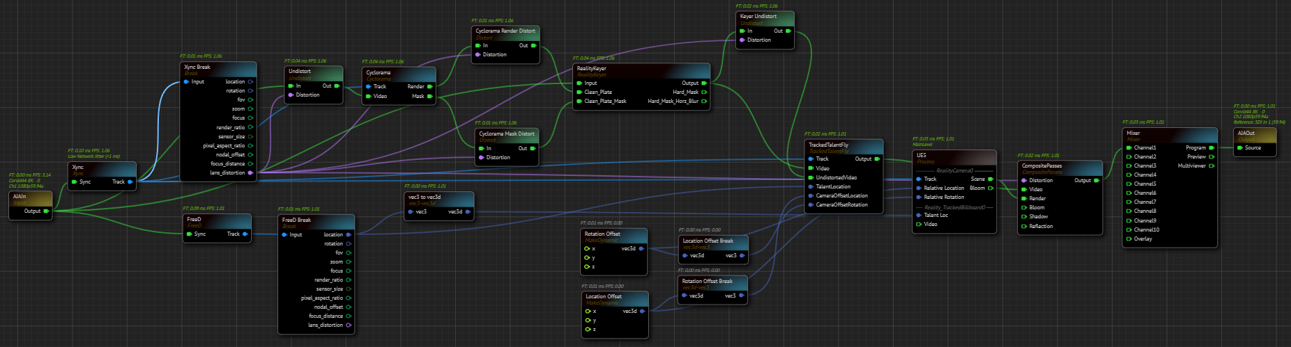
Adding UE5 Node to Canvas - Add a
UE5node to the nodegraph canvas. - Navigate to the Nodes panel and select UE5.
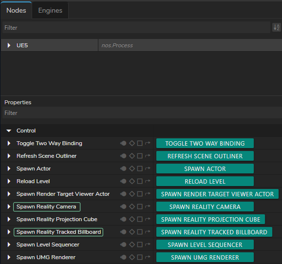
Spawning Reality Camera & Reality Track Billboard - Go to the Properties panel and click on the
Spawn Reality CameraandSpawn Reality Tracked Billboardfunctions.
-
Add AJAIn and AJAOut Nodes:
- Add
AJAInandAJAOutnodes.
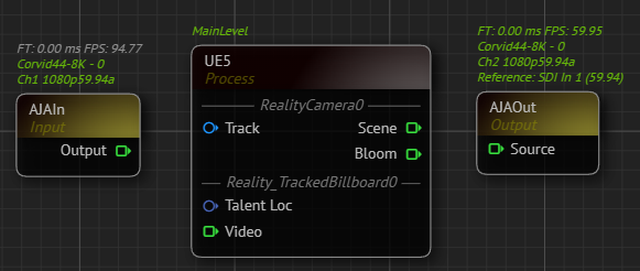
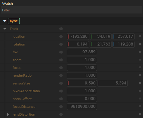
AJA Nodes with their Selected Details - Select your device details.
- Add
Adding Track Sources
- Add Tracking Nodes:
- Add your talent tracking and camera tracking nodes to the canvas. In our example, we use the
Xyncnode for camera tracking and theFreeDnode for talent tracking.
- Add your talent tracking and camera tracking nodes to the canvas. In our example, we use the
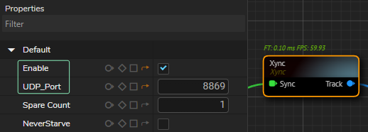
- Enable your tracking nodes by clicking on the
Enableproperty under theDefaultproperty group and define yourUDP Port.
- Connect Tracking Nodes:
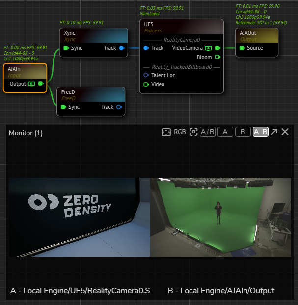
- Connect the
Trackoutput pin of theXyncnode to theTrackinput of theUE5node. - Connect the
Sceneoutput pin of theUE5node toSourceinput pin of theAJAOutnode. This connection lets you run the nodegraph and verify the Unreal scene and AJA input. - Use the Advanced Preview Monitor on the
AJAInnode'sOutputpin to check if you're receiving the correct signals.
- Check each track node for data flow by using Property Watch Panel. If corresponding nodes shows all zeros, re-check and verify your port number, track network connection, or device.
- Use Break Nodes:

- Add two
Breaknodes. - Connect the
Trackoutputs to your track nodes (In our case it is Xync and FreeD) into their Input pins. This extracts all data from the track nodes.
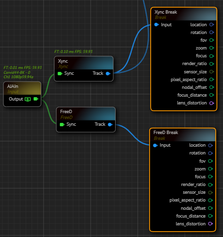
- Rename break nodes for better organization (e.g.,
Xync Breakfor camera tracking andFreeD Breakfor talent tracking).
- Add Undistort Node:
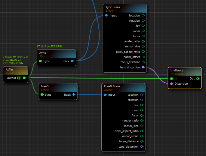
- Add an
Undistortnode. - Connect the
Outputpin of theAJAInnode to theIninput pin of theUndistortnode. - Connect the
Lens Distortionoutput of theXyncnode to theDistortioninput of theUndistortnode.
Cyclorama and Keyer
- Add Cyclorama Node:
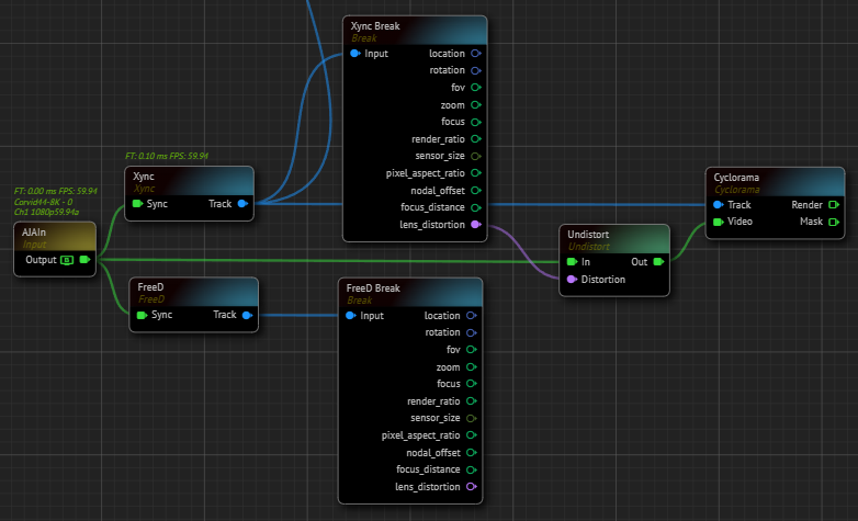
- Add a
Cycloramanode to the nodegraph canvas. - Connect the
Trackoutput pin of theXyncnode to theCycloramanode'sTrackinput. - Connect the
Outpin of theUndistortnode to theVideoinput pin of theCycloramanode.
info
At this point, make sure that there's no talent in your physical cyclorama since next steps involves taking clean plate.
-
Configure Cyclorama:
- Modify the
Cycloramanode's properties based on your studio setup (e.g., Geometry and Smoothness).
- Modify the
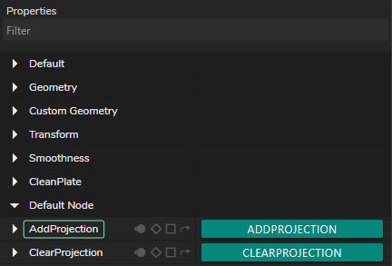
- Capture a clean plate by clicking on the
Add Projectionfunction.
- Add Distort Nodes:
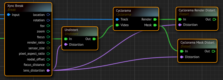
- Add two
Distortnodes to the nodegraph canvas. - Rename
Distortnodes for better organization (e.g., Cyclorama Render Distort and Cyclorama Mask Distort). - Connect the
Renderoutput pin of theCycloramanode to theCyclorama Render Distortnode. - Connect the
Maskoutput pin of theCycloramanode to theCyclorama Mask Distortnode. - Connect the
Xync Breaknode'sLens Distortionoutput to theDistortioninput of bothCyclorama Distortnodes.
- Add Reality Keyer Node:
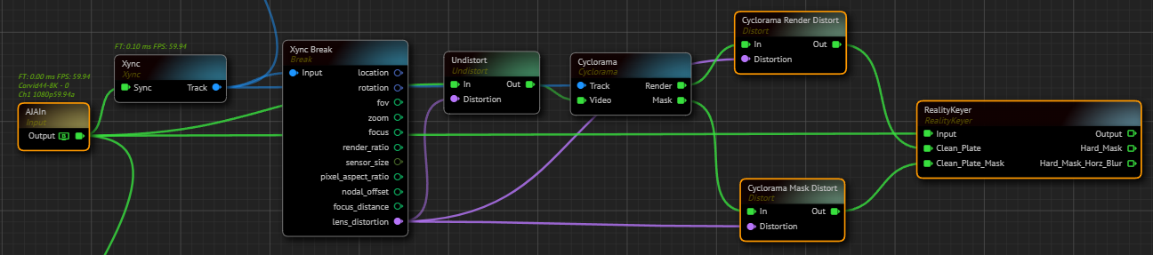
- Add a
Reality Keyernode to the canvas. - Connect the
AJAInnode'sOutputpin to theReality Keyer'sInputpin. - Connect the
Cyclorama Render Distortnode'sOutoutput pin to theClean Plateinput pin of theReality Keyernode. - Connect the
Cyclorama Mask Distortnode'sOutoutput pin to theClean Plate Maskinput pin of theReality Keyernode.
Exposing Engine Properties as Inputs
- Expose Reality Camera Properties:
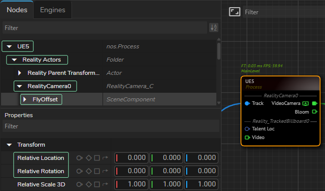
- Select the UE5 from the Nodes section, expand Reality Actors > Reality Camera, and select FlyOffset.
- Go to the Properties panel, expand the
Defaultproperty group. - Right-click on the
Relative Locationand select Show as input. - Right-click on the
Relative Rotationand select Show as input.
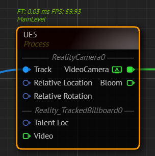
Your UE5 node should look like in the image above.
Casting with Dynamic Nodes
- Cast Talent Location:
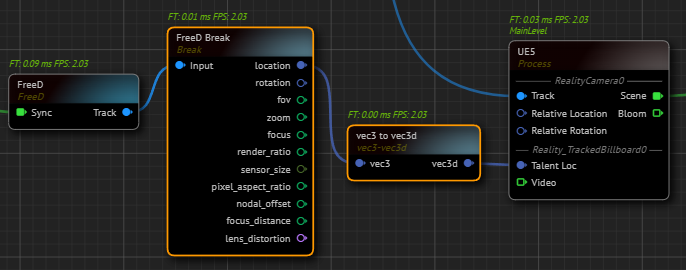
- Go to the
FreeD Breaknode, left-click and hold your mouse over theLocationoutput pin, then drag and drop it to open the Node Creation Menu. - Find vec3 to vec3d and select it. This creates a
vec3 to vec3dnode. - Connect the
vec3doutput pin of thevec3 to vec3dnode to theTalent Locinput pin of theUE5node. This allows the Tracked Billboard to receive X, Y, Z location data from your talent tracking (in our case, theFreeDnode).
- Create Rotation Offset:
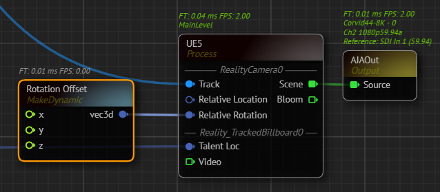
- Add a
Makenode to the canvas and rename it as Rotation Offset. - Connect the
Outputpin of theRotation Offsetnode to theRelative Rotationinput of theUE5node. This allows offsetting the relative rotation of the Reality Camera's pan, tilt, and roll. TheRotation Offsetnode'sXproperty represents roll,Yrepresents tilt, andZrepresents pan.
- Create Location Offset:
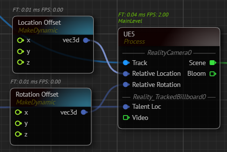
- Add a
Makenode to the canvas and rename it asLocation Offset. - Connect the
vec3output pin of theLocation Offsetnode to theRelative Locationinput of theUE5node. This allows offsetting the relative location of the Reality Camera. TheLocation Offsetnode'sXproperty represents the X direction,Yrepresents the Y direction, andZrepresents the Z direction.
Tracked Talent Fly Node
- Add Tracked Talent Fly Node:
- Add a
Tracked Talent Flynode to the canvas. - Add an
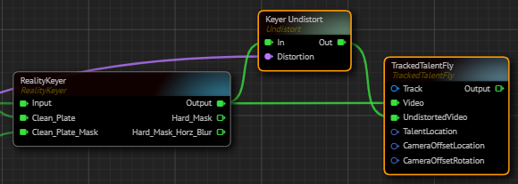
Undistortnode to the nodegraph canvas and rename it as Keyer Undistort. - Connect the
Lens Distortionoutput pin of theXync Breaknode toDistortioninput of theKeyer Undistortnode. - Connect the
Outputpin of theReality Keyernode toIninput pin of theKeyer Undistortnode. - Connect the
Outputpin of theReality Keyernode toVideoinput of theTrackedTalentFlynode. - Connect the
Outpin of theKeyer UndistorttoUndistortedVideoinput of theTrackedTalentFlynode.
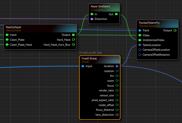
- Connect the
Trackoutput pin of theXyncnode to theTrackinput of theTrackedTalentFlynode. - Connect the
Locationoutput pin of theFreeD Breaknode to theTalentLocationinput of theTrackedTalentFlynode.
- Add Location and Rotation Offset Breaks:
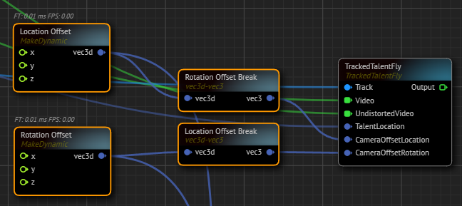
- Add a
vec3d to vec3node to the canvas and rename it asLocation Offset Break. - Connect the
Location Offsetnode'svec3doutput to theLocation Offset Breaknode'svec3dinput. - Connect the
vec3output of theLocation Offset Breaknode to theCameraOffsetLocationinput pin of theTrackedTalentFlynode. - Add another
vec3d to vec3node and rename it as Rotation Offset Break. - Connect the
Rotation Offsetnode'svec3doutput to theRotation Offset Breaknode'svec3dinput. - Connect the vec3 output of the
Rotation Offset Breaknode to theCameraOffsetRotationinput pin of theTrackedTalentFlynode.
Finalizing Setup
- Add CompositePasses Node:
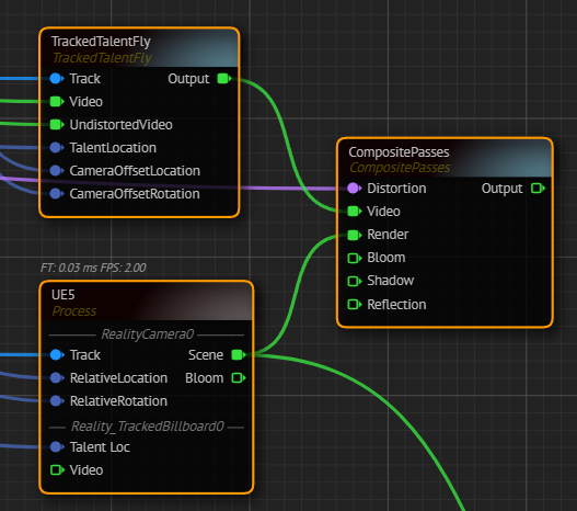
- Add a
CompositePassesnode to the canvas. - Connect the
Xync Breaknode'sLens Distortionoutput pin to theCompositePassesnode'sDistortioninput pin. - Connect the
Sceneoutput pin of theUE5node to theCompositePassesnode'sRenderinput pin. - Connect the
TrackedTalentFlynode'sTracked Talent Flypin to theVideoinput of theCompositePassesnode.
- Add Mixer Node:
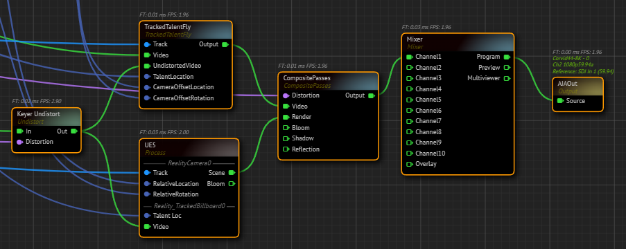
- Add a
Mixernode to the canvas. - Connect the
Outputpin of theCompositePassesnode to theChannel1input of theMixernode. - Connect the
Programoutput pin of theMixernode to theSourceinput pin of theAJAInnode. - Connect the
Keyer Undistortnode'sOutputpin toOutputinput pin of theUE5node. - Right-click on the
Programoutput pin of theMixernode and go to Monitor > Channel - A.
info
At this point, depending on your studio setup, you may need to map your transform (also known as negating) and adjust default values of your track nodes.
Your graph is now ready. Navigate to the Nodegraph Menu and click on the Save option.